Reducing low-frequency noise radiation from a concrete box girder bridge using acoustic short circuits
- Select a language for the TTS:
- UK English Female
- UK English Male
- US English Female
- US English Male
- Australian Female
- Australian Male
- Language selected: (auto detect) - EN
Play all audios:
ABSTRACT Low-frequency noise (20–200 Hz) radiated from concrete box girder bridges on urban viaduct railway lines is a significant source of disturbance to nearby residents. Many researchers
have investigated methods which can be used to effectively reduce this bridge noise. Currently, most of the methods are based on the principles of vibration isolation and/or absorption.
This paper, after modelling and analysing the contributions of various parts of a concrete box girder bridge to the total noise radiated from the bridge, presents a study on the potential in
bridge noise control of making holes to create acoustic short circuits on the bridge wings. It is found that by this means the bridge noise can be reduced by up to 6.8 dB at
standard-specified measurement points. Additionally, a 3dB-effectiveness distance ratio design method for acoustic short-circuiting is proposed, which effectively reduces bridge noise and
achieves stable noise reduction outcomes. SIMILAR CONTENT BEING VIEWED BY OTHERS AIRBORNE SOUND INSULATION PERFORMANCE OF LIGHTWEIGHT DOUBLE LEAF WALLS WITH DIFFERENT STUD TYPES Article Open
access 23 December 2024 ENHANCED LOW-FREQUENCY VIBRATION ISOLATION VIA INNOVATIVE DOUBLE-RESONATOR PHONONIC CRYSTALS Article Open access 24 May 2025 CUMULATIVE DAMAGE CHARACTERISTICS OF
TUNNEL INITIAL SUPPORT CONCRETE UNDER BLASTING LOAD Article Open access 23 January 2025 INTRODUCTION Viaduct bridges are commonly used to save urban space and reduce construction costs for
railway lines. Although urban railway trains run at relatively low speeds, normally lower than 120 km/h, due to high radiation efficiency of the bridge structure the resulting low-frequency
structural noise can be a significant source of disturbance for nearby residents1,2. The important frequencies are from 20 Hz to about 200 Hz. This noise can have negative impacts on
residents’ quality of life and even cause harm to their physical and mental health3,4. As a result, an increasing number of researchers are studying measures to effectively reduce the
structural noise of bridges5,6,7,8,9,10,11,12. Studied measures include those based on vibration isolation6,7,8,9, dissipation of vibrational energy by constrained layer damping10, Influence
of box-girder and U-shaped sections on bridge noise11, reduction of wheel–rail excitation sources12, etc. Measures based on the above principles, such as steel spring floating slab track13,
normally have good noise reduction effect only at the early stage of application. There is another issue, that these measures may increase rail vibration and make it prone to generate bad
abrasion such as rail corrugation14. Generation of rail corrugation will intensify wheel-rail interaction15 and, as a result, largely or completely offset the noise reduction effect, or even
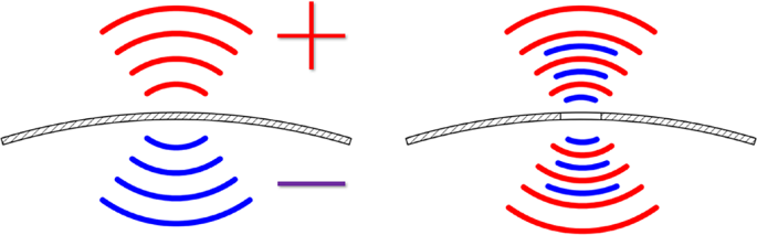
make the situation worse. Conversely, acoustic short circuit16,17 is a method to reduce the radiation efficiency of a structure by cancellation of the sound waves on the two sides of the
structure. The principle of acoustic short circuit is illustrated in Fig. 1. When the panel vibrates, there is positive (+) acoustic pressure on one side and negative (-) one on the other
side. By establishing acoustic connectivity for the two sides, the acoustic pressures cancel each other out, thereby achieving noise reduction. This method avoids altering the track and
track, and thereby wheel-rail interaction, enabling it to sustain high levels of noise reduction over extended periods. Furthermore, it may also reduce the construction materials and costs
of the bridge structure. Acoustic short circuit has been employed to address the issue of noise reduction in plate structures. Putra and Thompson16,18 utilized the acoustic short-circuit
principle to propose a formula to calculate sound radiation efficiency for rectangular perforated plates. They showed that, when hole sizes were uniform, a higher perforation ratio resulted
in lower sound radiation efficiency; when the perforation ratio was consistent, a smaller hole size resulted in a lower sound radiation efficiency. This indicates that noise reduction
effectiveness based on open area ratio designs is inherently unstable, underscoring the urgent need for an acoustically-based method of designing acoustic short-circuiting. Although previous
studies have explored the concept of acoustic short-circuiting, the majority have focused on its effect in reducing the sound radiation efficiency of panels. There has been little
exploration into the potential of acoustic short-circuiting for mitigating bridge noise. Research shows that, for the most used bridge structure in China, the concrete box girder bridge, the
main sound sources of bridge noise are the top and wing plates18,19. If noise from the wing plates is removed, the sound pressure level at a railway noise assessment point can be reduced by
about 6–8 dB. Owing to the weak directivity of low-frequency sound, sound radiation directions on both sides of the ring slab are opposite to each other, that is, the phase difference
between them is 180°16. Because the wavelength of a low-frequency sound wave is long and its diffraction ability is strong15, it can be diffracted easily using opening holes to offset the
sound pressure on both sides. Therefore, openings on the wing plate are conducive to reducing low-frequency sound radiation. The prediction of bridge noise can be a complex process that
involves two main steps. The first step is to obtain bridge vibration by solving the vehicle-track-bridge interaction problem1,20,21,22,23. The bridge vibration calculated is used as
boundary condition for the second step. The second step involves predicting the sound radiation of the bridge. Due to the complexity of box bridge structures, numerical methods such as the
finite element method (FEM) and boundary element method (BEM)24 are often used. Considering the above research, the purpose of this paper is to explore the noise reduction effect of acoustic
short circuiting for bridge noise. To accomplish this objective, the paper is organized as follows: in Sect. 2, the moving-roughness approach to wheel/rail interaction and the finite
element method are utilized to construct a vibro-acoustic model for a 24 m span single-track bridge. The predicted results of the model are compared with experimental results in Sect. 3, to
demonstrate the usefulness of the models. Based on these results, the contributions of various components of the bridge are analyzed to help determine which plates have better acoustic short
circuit control effects (Sect. 4). THE VIBRO-ACOUSTIC MODEL OF THE BRIDGE The prediction process is delineated in Fig. 2 and comprises two primary facets: the vehicle-track-bridge
interaction component discussed in Sect. 2.1 and the acoustic radiation component detailed in Sect. 2.2. Achieving precise predictions of bridge noise demands a thorough grasp of these two
components and their interplay. VEHICLE–TRACK–BRIDGE INTERACTION Both the moving-roughness approach1 and the moving-vehicle approach20,21 have been used to study interactions between
vehicles, tracks, and bridges. The former is much simpler than the latter. Since the trains considered in this paper are urban railway trains at speeds lower than 120 km/h, the
moving-roughness approach should be appropriate, as demonstrated in References1,4,25. VEHICLE MODEL Here, the prediction of vehicle dynamics is used to calculate the vibration of vehicles
owing to a unit harmonic wheel–rail force (0.5 N at each wheel), generating a receptance matrix for the vehicles at the wheel–rail contact points. The studied vehicle is the one forming the
urban D-type train running at 120 km/h. Due to the literature indicating that the frequencies associated with train primary and secondary suspensions, as well as the nodding motion of the
train and bogie, are relatively low (Within 20 Hz)26. Therefore, this study disregards the coupling of wheelset on the vehicle, focusing solely on the wheelset in the vehicle system25. THE
TRACK-BRIDGE MODEL Frequencies concerned with bridge noise are high for bridge vibration, and at these frequencies it is inappropriate to model the bridge as a beam or using beam elements.
The transition section of the chamfer makes the use of shell elements also inappropriate. Therefore, in this paper, we used SOLID186 in software ANSYS (20-noded high-order hexahedral
element) to model a single-line simply supported box girder, with a span of 24 m. The rail layout above the bridge and box girder structures are shown in Fig. 3. The track structure on the
bridge is a ballastless slab track. The thickness of the slab is 0.2 m, the thickness of self-compacting concrete is 0.16 m, the rail type is CN 60 rail, and the fastener type is WJ-7. The
fastener interval on the slab was 0.6 m, and 8 sets of fasteners were installed on each slab. Other parameters are shown in Table 1. The finite element model of the track-bridge system was
established using the commercial finite element software ANSYS. The rail was simulated using BEAM 188 elements, the fastener was simulated using a COMBINE 14 spring damping element, and the
slab and self-compacting concrete layer were simulated using a SOLID 186 elements. ROUGHNESS EXCITATION Wheel and rail roughness is the main excitation source for wheel-rail system
vibration. For the calculation of bridge structure noise, the frequency range of the wheel-rail interaction forces calculated in this paper is between 16 and 226 Hz. The corresponding track
roughness spectrum has a wavelength between 0.15 and 2.08 m (120 to 160 km/h). To achieve the wavelengths of the track roughness spectrum required in this paper, the measured track
spectrum27 of the high and low irregularities of a ballast track of a city rail bridge line (train speed, fastening system, etc. are the same as in this paper) is spliced with the track
spectrum of ISO-3095 (2013 version) at short wave wavelengths as shown in Fig. 4. Both the wheel/rail contact stiffness and the contact filter effect28 were considered. This is done by
assuming that the PSD is a linear function of frequency in all bands except the one with the shortest centre wavelength for which the PSD is assumed to be uniform. The amplitude of the
roughness component at a required wavelength is given by the square root of the integration of the PSD within the associated octave wavelength band. WHEEL–RAIL INTERACTION Figure 5 shows the
coupled vibration model for wheelset–track–box girder to simulate the wheel–rail interactive force and its transmission to a box girder when one carriage and four wheelsets act on a span
bridge. This article considers the interactive impacts between four wheelsets on a specific span bridge. No. 1, 2, 3, and 4 are the position numbers of the wheelset acting on the rail. When
considering the interaction between wheelsets29: $$\left[ {Y_{{\text{W}}}^{l} \left( \omega \right) + Y_{{\text{C}}}^{l} \left( \omega \right)} \right]F^{l} \left( \omega \right) +
\sum\limits_{{k = 1}}^{4} {Y_{{\text{R}}}^{{lk}} \left( \omega \right)} F^{k} \left( \omega \right) = r^{l} \left( \omega \right),$$ (1) where \(Y_{{\text{R}}}^{lk}\) represents the vertical
displacement receptance of the rail at the _l_th wheelset position when the unit simple harmonic force (i.e. a unit force 0.5 N acts on the left and right rails at each wheelset position)
acts on the _k_th wheelset position. This receptance is affected by the track and the bridge. \(Y_{{\text{w}}}^{l}\) represents the vertical displacement of the _l_th wheelset under unit
simple harmonic force. \(Y_{{\text{C}}}^{l}\) indicates the vertical displacement receptance of the contact spring at the position of the _l_th wheelset, _F__l_ is the wheel–rail force
receptance at the position of the _l_th wheelset, and _r__l_ is the receptance of wheel–rail combined roughness at the position of the _l_th wheelset. As indicated in Eq. (1), the changes in
wheelset and rail vertical receptances will directly affect the wheel–rail interaction force. Figure 6 depicts the vertical receptance and the sum of the wheelset, rail, and contact spring
receptances (called the system receptance). The results presented in Fig. 6 demonstrate that: * The system receptance is primarily influenced by the wheelset receptance at frequencies below
30 Hz. Between 30 ~ 120 Hz, the system receptance is jointly influenced by the wheelset and rail receptances. Between 120 ~ 200 Hz, the system receptance is primarily influenced by the rail
receptance. * At 60 Hz, since the receptances of the wheelset and rail are equal in magnitude but opposite in sign, resulting in a dip in the total receptance. This frequency is the
resonance frequency of the wheel–rail system (P2 wheel–rail force frequency). There is formula to estimate this frequency in Ref30. ACOUSTIC RADIATION MODEL OF THE BRIDGE STRUCTURE Once the
vibration of the bridge has been calculated, the sound field generated by the bridge vibration can be predicted, either using the acoustic boundary element method or using the acoustic
finite element method. The latter was used in this paper. To achieve accurate calculations, the element size on the bridge surface is shorter than 0.28 m, which is approximately 1/6 of the
shortest acoustic wavelength at 200 Hz with a sound speed of 340 m/s. Furthermore, to capture the fine acoustic structures at the hole locations, local refinement was applied to the acoustic
finite element model, ensuring that one circle comprises a minimum of 16 elements. The bridge FEM with holes with a diameter of 0.75 m and a spacing of 1.5 m on the wing plate is shown in
Fig. 7(a) and the acoustic FEM is shown in Fig. 7(b). Perfectly Matched Layers (PML) have been utilized on the outer surface of the acoustic finite element model of the bridge to prevent the
reflection of sound waves. The literature on acoustic modelling for bridge structural noise reveals that the track slab is often excluded from the model. However, in this paper we include
the slab in the calculation of bridge noise. There are four reasons for this: (1) based on Ref31, the sound radiation of a slab structure is concentrated mainly at the same frequency range
as bridge noise, therefore, measured noise in this frequency range is contributed by both the slab and the bridge with no way to separate their contributions from each other; (2) Ref11
suggests that the thickness of the top plate of the bridge has a significant impact on bridge noise. Failing to consider the slab while establishing the bridge sound radiation model would
result in an overestimation of the bridge noise; (3) given the strong connection characteristics and similar material properties of the slab and bridge structures, which are linked by
self-compacting concrete, they should be considered as a single entity rather than separate bodies. Considering the above reasons, this article presents a bridge acoustic finite element
model that incorporates the slab structure. It should also be noted that, the ground is not taken into the model, since the assessment points are at heights 7 m above the ground surface.
VERIFICATION OF THE MODEL DESCRIPTION OF THE MEASUREMENT The noise measurement point (S) show the approximate location of the sound level meter/analyzer in the span of the bridge in Fig. 8.
Under the shielding effect of the bridge, the rolling noise of the wheel-rail and aerodynamic noise need to bypass the bridge cross-section to affect the measurement points. Therefore, their
contribution can be significantly reduced, resulting in the measured noise primarily consisting of bridge noise32 Li et al. 2013). A sampling frequency of 8192 Hz and a band-pass filtering
range of 10 ~ 1000 Hz are used. According to standard EN ISO 3095 − 2013 _Acoustics - Railway applications - Measurement of noise emitted by railbound vehicles_ and GB/T GB/T 5111 − 2011
_Acoustics -Measurement of noise emitted by railbound vehicles_, the remaining noise observation points (N1, N2, and N3) are utilized as assessment points for evaluating the efficacy of
noise reduction measures in Sect. 4. The positions N1, N2, and N3 were chosen for evaluation and design in this paper because they are the most commonly used assessment points in both field
tests and standards. The noise contour plots reveal the impact of the bridge openings on noise distribution before and after their implementation, and these points effectively represent the
nearby trends. However, for specific sensitive locations, a redesign would be necessary. COMPARISON BETWEEN MODEL PREDICTION AND IN-SITU MEASUREMENT This paper uses the in-situ measurement
results to verify the model. Figure 9 shows the bridge noise at the measurement point under the bridge. In Fig. 9, Due to the vehicle’s operational state, there is some uncertainty in the
low-frequency testing33. Additionally, discrepancies between input parameters and actual parameters, as well as acoustic boundaries such as ground reflections, contribute to the differences
between the measured and predicted results in the low-frequency range (below approximately 40 Hz). Fortunately, the measured and predicted results are in good agreement for frequencies
higher than 50 Hz, ensuring the usefulness of the prediction model. The peak at 63 Hz is due to the P2 resonance of the vehicle/track system. INFLUENCE OF ACOUSTIC SHORT CIRCUIT ON BRIDGE
NOISE This section analyzes the effect of acoustic short circuits created on the wing plate. To do so, the contribution of various parts of the bridge is analyzed first. DIVISION OF THE
BRIDGE The bridge structure can be simplified to consist of several parts, i.e., one top plate, two webs, one bottom plate, and two wings. The box formed by them provides the necessary
structural stiffness and strength, while the wings serve as pedestrian walkways. The various plates of the box girder are depicted in Fig. 10. Analyzing the contribution of each part to the
total bridge noise help determine to which part noise control measures should be applied. CONTRIBUTIONS OF THE VARIOUS PARTS OF THE BRIDGE Contributions of the various parts of the bridge to
the bridge noise spectra at observation points N1 and N3 are shown in Fig. 13. The contribution of one part is calculated by setting the vibrational velocities of all the other parts to
zero. A brighter color indicates a higher contribution. Contributions of the various parts of the bridge to the overall bridge noise at observation points N1 and N3 are shown in Fig. 12. Two
main observations can be made according to Fig. 11. Firstly, For each part, the most contributing frequency range is 50 ~ 70 Hz due to P2 resonance. Secondly, when the sound radiation
contribution of the plate becomes negative at certain frequencies, it is because at those frequencies, the sound pressure of the plate at that specific location is negative. As depicted in
Fig. 12, except for the S1 measurement point, the two wings of the box girder are the primary noise contributors, producing at least 5 dB more noise than the other three parts. This
observation suggests that noise reduction on the bridge could be achieved by minimizing noise radiation from the wings. Given that the wings are designed primarily for pedestrians,
modifications to the wings are much more flexible for bridge noise reduction. The effect of making the wing plates perforated on bridge noise is investigated in the next section. INFLUENCE
OF WING PLATE OPENING INFLUENCE OF WING PLATE OPENING ON THE NOISE OF BOX GIRDER STRUCTURE To better understand the changes in sound radiation characteristics of the box girder before and
after creating openings on the wing plates, we conducted a series of experiments. Specifically, we created a circular hole with a diameter of 0.75 m on both the right and left sides of the
wing plate located at the midspan position of the box girder. Figure 13 depicts the positions of the wing plate openings as well as the sound field points. The opening approach used for the
wing plate was a vertical through-hole. In order to ensure that the functionality of the bridge wing plate is not affected after the openings are made, mesh-perforated steel plates can be
used to cover the openings, thus enabling unimpeded use of the wing plate. Upon creating an individual round hole with a diameter of 0.75 m on each side of the wing plate located at the
midspan position, Fig. 14 displays the contour map of the total sound pressure level difference at the sound field points adjacent to the wing plate, before and after the creation of the
wing plate openings on the box girder. The sound field points is situated in the orange area illustrated in Fig. 13. As depicted in Fig. 14, the two black dotted lines illustrate the
position of the openings, while the black and red solid lines represent the contour lines of the total sound pressure level reduction of 5 and 3 dB, respectively. The distribution reveals
that the sound pressure level directly above the wing plate opening decreases significantly, up to approximately 9 dB, whereas the total sound pressure level gradually decreases along the
opening position. Subsequently, the opening spacing is designed based on the range of total sound pressure level reduction of 3 dB. Figure 14 demonstrates that when the wing plate opening
diameter is 0.75 m, the horizontal distance of the red contour line with a total sound pressure level reduction of 3 dB is about 1.5 m, which is twice the opening diameter. Based on this,
the opening spacing of the wing plate is determined. When the opening diameter is 0.75 m, the opening spacing is 1.5 m, and there are 16 openings in each wing plate. The total opening area
of the left and right wing plates is 4.5π m2. The finite element model of the track box girder after the opening is displayed in Fig. 15. The distribution of the total sound pressure level
radiated by the observation points at the midspan cross-section before and after the opening of the wing plate is presented in Fig. 16. Given the symmetric nature of the bridge structure,
only half of the sound field distribution is presented in the paper. Figure 16 reveals the following observations: (1) By comparing the distribution of the overall sound-pressure-level
radiation for the cross-section before and after creating wing plate openings, the sound pressure level in the area above the wing plate after creating the opening exhibits an apparent
decrease; the wing plate opening location can be clearly observed from the distribution of sound pressure level. (2) Fig. 16 (c) shows the distribution depicting overall sound pressure level
variations before and after creating wing plate openings. The red line in the diagram denotes the contour line of the 5 dB change in total sound pressure level, and the black line denotes
the contour line of the 8 dB change in the total sound pressure level. From the distribution, we can clearly determine the sound pressure level for the cross-section radiation impacted by
the wing plate opening. By comparing with a single hole opened earlier at one side of the wing plate, when 16 holes are opened at one side of the wing plate, the overall sound pressure level
decreases more distinctively near each pore, indicating that when multiple holes are opened on the wing plate, an interaction occurs between holes to generate certain overlaying effects.
(3) The created wing plate openings significantly affect the sound pressure level in the area above the right side of the box girder, whereas the influence on the bottom zone of the box
girder is considerably small. A noise-amplifying phenomenon for the box girder structure occurs in certain areas beneath the bridge. The phenomenon has been attributed to openings in the
bridge wing plate, and the specific reasons await further investigation. (4) Fig. 16(d) includes an analysis of the bridge’s radiated sound power, indicating its capacity to emit noise. The
data suggest that acoustic short-circuiting has minimal effect on the bridge’s radiated sound power, and may even lead to an increase. Nevertheless, when considered together with Fig.
16(a)-(c), it is clear that the sound field distribution is modified, thereby reducing the sound pressure at critical sensitive points. While there might be some amplification at the top and
bottom sections of the bridge, these areas are fortunately free of residential development and are not primary concerns for external noise standards. To further investigate the influence on
the spectrum of external noise reference point N1 before and after creating wing plate openings, Fig. 17 shows the sound pressure level spectrum before and after creating the wing plate
openings. Figure 17 shows that after creating the wing plate opening, although the impact on the bridge’s radiated sound power is minimal, there is significant noise attenuation at the
external noise reference point N1, particularly in the 25–160 Hz range. Notably, at the primary frequency of 63 Hz, the wing plate opening reduces the bridge noise by approximately 8.0 dB,
resulting in a total sound pressure level reduction of 6.1 dB. Table 2 compares the total sound pressure levels of box girder structural noise at reference positions N1, N2, and N3 before
and after creating the wing plate openings. Table 2 shows that after creating wing plate openings, the overall sound pressure levels of sound radiation decreased by 6.1, 6.8, and 3.2 dB at
positions N1, N2, and N3, respectively, implying that creating openings using this method can effectively reduce the structural noise of box girders. Through the earlier analysis, after the
calculation of the structural noise of the box girder with an opening diameter of 0.75 m and opening spacing of 1.5 m on both sides of the wing plate, we observe that adopting this design
scheme can effectively reduce the noise pressure level of box girder structure at positions N1, N2, and N3. To verify the accuracy of the designed scheme, this paper follows this design
concept to investigate the noise reduction effect of box girders after altering the opening diameter of the wing plate. First, the sound radiation characteristics are analysed when a round
opening is created on the wing plate on each side at the midspan of the box girder. The centre of the opening position of the wing plate of the box girder is the same as above. Considering
the strength and safety of bridges, the size of the openings should not be excessively large. To facilitate comparison between design schemes based on material or geometric considerations,
such as open area ratios, and those based on acoustic design, this paper selects three diameters—0.25, 0.35, 0.5, and 0.75—as the parameters for consideration. Figure 18 shows the
distribution of the total sound pressure level difference at the observation points before and after the opening of the three diameters. In the current paper, the open area ratio has been
used as a key parameter to evaluate the effectiveness of acoustic short-circuiting. However, the open area ratio primarily addresses acoustic issues from a material or geometric perspective.
Moreover, some studies16,17,18 have indicated that even with the same open area ratio, the size of the openings can significantly affect noise reduction performance. Therefore, this paper
introduces the concept of equal noise reduction contours(3dB-effectiveness distance ratio concept, that is, the ratio of the transverse attenuation range of the contour line with the total
sound pressure level reduced by 3 dB to the size of the opening diameter. For example, when the opening diameter is 0.75 m, the transverse attenuation range of the contour line with 3 dB is
1.5 m, and the 3dB-effectiveness distance ratio is 1.5/0.75 = 2) to assess acoustic short-circuiting from an acoustic perspective, offering a new direction for evaluating acoustic
short-circuiting. The 3dB-effectiveness distance ratio method can characterize the extent to which the sound pressures on both sides of the bridge plates cancel each other out after openings
are introduced. In Fig. 18, the two black dashed lines in the distribution represent the opening position, and the red solid line is the contour line with the total sound pressure level
reduced by 3 dB. The figure shows that the larger the opening diameter of the circular hole of the wing plate, the larger the coverage area of the 3 dB contour. When opening diameters for
wing plates are 0.25, 0.35, 0.5, and 0.75 m, the relation between wing plate opening diameter and 3dB-effectiveness distance ratio are as shown in Fig. 19. Figure 19 shows that the larger
the opening diameter, the larger the 3dB-effectiveness distance ratio, and the slope of the 3dB-effectiveness distance ratio first increases and then decreases. According to the relation
between wing plate opening sizes and 3dB-effectiveness distance ratio, and using the above design method when the wing plate opening is 0.75 m, we next design an opening spacing when the
wing plate opening size is 0.5 m. Therefore, when designing panels with a uniform distribution of openings at a constant open area ratio, excessively large openings can reduce the slope of
the 3dB-effectiveness distance ratio, leading to decreased noise reduction performance. This phenomenon explains the finding in the Ref16,18 that larger openings are associated with less
effective noise reduction. It can also be inferred that there exists an optimal opening diameter for a specific structure. For the bridge in this study, the optimal opening diameter for
maximum effectiveness is between 0.4 and 0.6, where the slope of the 3dB-effectiveness distance ratio is maximized. Figure 19 indicates that when the wing plate opening diameter is 0.5 m,
the 3dB-effectiveness distance ratio is 1.74, the lateral distance of the contour lines with a total sound pressure level difference of 3 dB is 0.87 m. To create a uniform opening on the
wing plate of a 24 m box girder as much as possible, we design the opening spacing between holes on the wing plate as 0.8 m; here, there are a total of 60 holes on both sides of the wing
plate with the overall opening area of 3.75π m2. The structural model of track–box girder after creating openings is shown in Fig. 20. Similarly, when the opening diameter for the wing plate
is 0.6 m, the 3dB-effectiveness distance ratio reaches 1.8; when we derive the opening diameter of the wing plate is 0.6 m according to the design method, the hole spacing between openings
should be 1.08 m. Therefore, when the design of the wing plate opening is 0.6 m, 44 uniform openings are created on both sides of the wing plate of the 24 m box girder. Here, the overall
opening area is 3.96π m2. To further explore the influence on the spectrum of external noise for reference point N1 after creating a wing plate opening according to the method of
3dB-effectiveness distance ratio. The sound pressure level spectrum and the total value for N1 are given in Figs. 21 and 22, respectively. In Figs. 21 and 22, ‘d’ represents the opening
diameter. Figures 21 and 22 illustrate that, despite the differences in opening diameter, spacing, and area (3.75π m2, 3.96π m2, 4.5π m2) among the three wing plate opening methods, the
noise reduction effects at the three observation points are remarkably consistent. For instance, the noise reduction at N1 is 6 dB, with the maximum overall difference being only 0.5 dB and
the largest spectral difference being 2.57 dB (at 50 Hz). This consistency indicates that the use of the 3dB-effectiveness distance ratio method for designing acoustic short-circuiting on
the bridge wing plates yields an effective and stable noise reduction outcome. It is worth noting that the open area ratios of these three methods differ, which indirectly highlights the
challenge of achieving consistent results with acoustic design schemes based on material or geometric methods. INFLUENCE ON BOX GIRDER STRUCTURAL NOISE OF THE OPENING DIAMETER OF THE WING
PLATE Based on the relationship described in the previous section about the opening diameter and 3dB-effectiveness distance ratio, a preliminary design is conducted on the selection of the
wing plate opening diameter and opening spacing. After calculation, this design scheme is observed to have a good effect on reducing box girder structural noise. Here, it is necessary to
guarantee the same perforation ratio of various design schemes for the wing plate; The perforation ratio refers to the opening area divided by the total area. Subsequently, the overall sound
pressure level of the box girder structure at positions N1, N2, and N3 are calculated. Table 3 describes the opening schemes for wing plates when designing a 24 m simply supported box
girder bridge with the same perforation ratio. Figure 23 shows the spectrum at N1 calculated using the opening scheme with the same perforation ratio, and the overall sound pressure levels
at various positions are shown in Fig. 24. Figures 23 and 24 show that under the circumstance of the same perforation ratio, the noise reduction effect of the three wing plate openings on
the box girder structure is similar (about 3 dB of bridge noise is reduced at observation point N1), and the maximum difference of the total value is 0.7 dB, and the maximum difference of
the spectrum is 3 dB. By comparing Figs. 22 and 24, we observe that the noise reduction effect of bridge noise with the opening method of 3dB-effectiveness distance ratio is comparable to
that of the perforation ratio. Therefore, the opening method of 3dB-effectiveness distance ratio provides another option for the design of acoustic short circuits in bridges. To further
compare the impact on the bridge noise difference by two different opening methods, Fig. 25 shows the relationship between maximum difference and spectrum of the three opening schemes for
bridge noise based on overall opening methods. Figure 25 demonstrates that, within the entire frequency range, the noise reduction stability achieved through the 3 dB-effectiveness distance
ratio-based opening method for bridge noise consistently surpasses that achieved via the perforation ratio, with the exception of the 50–63 Hz range. It is worth noting that using
alternative methods, such as concentrated openings, at the same open area ratio can lead to reduced noise reduction effectiveness. INFLUENCE OF WEB OPENING The previous section has mentioned
the opening design of the wing plate of a box girder. We observe that a reasonable opening scheme can effectively reduce box girder structural noise. Next, the box girder web is used as a
research target to explore the noise reduction effect generated by different opening positions of the box girder. VARIATION IN BOX GIRDER STRUCTURAL NOISE AFTER CREATING WEB OPENINGS As the
box girder web primarily has the role of support and weight bearing, focus should be given to the opening size and opening spacing when creating round openings on both sides of the box
girder web. When designing the web opening, the article refers to the relevant requirement of opening round holes on the concrete structure web in _Constitutional Manual of Practical
Concrete Structures_34 and designed three web opening schemes, shown in Table 4. Figure 26 is a finite element model of a track–box girder structure with web opening scheme 1; it has 48
mini-holes on both sides of the web. As the box girder structure has a cavity, the phenomenon that the interior of the cavity is connected with the outside will occur after the opening of
the box girder web. Here, the air inside the cavity must be considered when calculating the noise radiation of the box girder structure. Therefore, the acoustic finite element grid inside
the cavity must be divided. Figure 27 shows the prediction model of the noise radiation of the box girder structure when the box girder web is opened. The acoustic boundary conditions at
both ends of the cavity are defined as full sound absorption boundary conditions. Taking web opening scheme 1 as an example, Fig. 28 shows the 1/3 octave sound pressure level curve at
position N1 before and after web opening. No significant difference is observed between the change law of the sound pressure level curve at the observation points after the web opening and
that before the opening. To compare the generated effect on reducing box girder structural noise by adopting the three schemes, Table 5 provides the overall sound pressure level of box
girder structural noise at N1, N2, and N3 of the three different web opening schemes. Table 5 implies that the three web opening schemes have no apparent effect on reducing the total sound
pressure level of box girder structural noise at three standard points, and a small increase occurs in the total sound pressure level at individual observation points. The reasons for their
failure may be as follows: * (1) The sound pressure within the box girder cavity may be higher than that outside the cavity. After creating openings, the sound pressure inside the cavity may
leak to the exterior of the cavity and resulting in an increase rather than a decrease in the sound pressure level at the standard point. * (2) The calculation in Sect. 3 of the sound
radiation contribution of various plates of box girder for three standard observation points shows that the sound radiation contribution of the wing plate is significantly greater than that
of the web; hence, the opening on the web cannot effectively reduce the overall sound pressure level at various observation points. * (3) The hole size of the openings at both sides of the
web is significantly small, which does not generate apparent impacts for large-scale box girder structures. RESULT ANALYSIS OF WEB OPENINGS Here, we analyse the result indicated in the
previous section that the box girder structural noise does not generate effective noise reduction effects after web opening. Two positions within the cavity of the box girder span are
selected as the reference to calculate the overall sound pressure level within the cavity; the results attained are 104.9 and 103.5 dB. This means that the noise within the cavity of the box
girder structure is very large, which is significantly more than the overall sound pressure at the standard measurement point. Hence, after web opening, the phenomenon of sound leaking out
via the apertures occurs in the cavity, which results in the web opening not creating a significant effect on reducing box girder structural noise. Next, we analyse sound radiation of box
girder structural noise before and after web openings. The calculation and design scheme when creating openings for the box girder wing plate are combined contextually. First, a round hole
with a diameter of 0.5 m is created at the midspan on both sides of the box girder wing plate. The track–box girder structure and the side layout after the web opening at both sides are
shown in Fig. 29. Figure 30 shows the distribution of the sound pressure level after 0.5 m round holes are opened on both sides of the web. The figure shows that when a circular hole is
opened at the midspan on both sides of the web, the sound pressure level does not change significantly after the opening, nor does the total sound pressure level near the opening decreases
significantly, and even the total sound pressure level near the opening increases slightly after the opening. This is because the sound pressure inside the cavity leaks outward after the
opening of the web, which offsets the noise reduction effect after opening the web. Next, we analyse the sound radiation characteristics for the box girder with web openings created on both
sides, with an opening diameter of 0.5 m and spacing of 1 m. Here, 48 holes are created on both sides of the web. Figure 31 depicts the Distribution of the overall difference in the radiated
sound pressure level at the observation points after web openings. The diagram shows that only the overall sound pressure level adjacent to the holes has been reduced in a small receptance.
The total sound pressure level increases significantly in two areas on the left and right sides from the midspan of the box girder. This is because the high sound pressure level inside the
cavity produces a sound leakage, and the leakage has a significant impact on the area near the web. In summary, creating holes on the web to reduce box girder structural noise is not
feasible; it can result in sound pressure leakage in the cavity and reduce the effects of web opening, resulting in a significant increase in the sound pressure level adjacent to the web.
CONCLUSION The present study investigates a practical solution to mitigate structural noise in box girder bridges. By applying the acoustic short-circuit principle, the research designs
openings in the wing plates and web of a 24 m single-line simply supported box girder and examines their noise-reducing effects in terms of opening size, spacing, and positions. The
following conclusions are drawn: * (1) A circular hole is opened on both sides of the midspan position of the wing plate of the box girder. The diameter of the circular hole is directly
proportional to the 3dB-effectiveness distance ratio. The 3dB-effectiveness distance ratio method can provide guidance on determining the relationship between the diameter of other openings
and the 3dB-effectiveness distance ratio. * (2) The wing plate opening scheme designed based on the 3dB-effectiveness distance ratio is effective in reducing box girder structural noise.
When the wing plate opening diameter is 0.75 m and opening spacing is 1.5 m, the overall sound pressure level reduction at N1 is 6.1 dB, at N2 is 6.8 dB, and at N3 is 3.2 dB, indicating a
good noise reduction effect. * (3) The noise reduction effect achieved through the 3dB-effectiveness distance ratio method is comparable to that obtained using the perforation ratio method.
However, the results from the 3dB-effectiveness distance ratio method are notably more stable. Therefore, this approach offers an alternative option for designing acoustic short circuits in
bridges. * (4) The approach of web opening is not effective in reducing box girder structural noise. After holes are opened on both sides of the web of a box girder, the sound leakage due to
the high sound pressure level within the cavity of the box girder leads to an increase in the sound pressure level in the surrounding of the web. DATA AVAILABILITY All of data, models, or
code that support the findings of this study are available from the corresponding author upon reasonable request. REFERENCES * Thompson, D. J. _Railway Noise and Vibration: Mechanisms,
Modelling and Means of Control_ (Elsevier, 2009). * Aloisio, A., Rosso, M. M. & Alaggio, R. Experimental and analytical investigation into the effect of ballasted track on the dynamic
response of railway bridges under moving loads. _J. Bridge Eng. _27(10), 04022085 (2022). Article Google Scholar * Zhang, J. et al. Experimental Studies of Extracting Bridge Mode Shapes by
Response of a Moving Vehicle. _J. Bridge Eng. _28(11), 04023076 (2023). Article ADS Google Scholar * Zhang, X., Li, X., Hao, H. & Li, D. W. Y. A case study of interior low-frequency
noise from box-shaped bridge girders induced by running trains: Its mechanism, prediction and countermeasures. _J. Sound Vib. _367, 129–144 (2016). Article ADS Google Scholar * Daniel
Costley, R., Diaz-Alvarez, H., Mckenna, M. H. & Jordan, A. M. Vibration and Acoustic Analysis of a Trussed Railroad Bridge under Moving Loads. _J. Vib. Acoustics: Trans. Asme _137(3),
617–629 (2012). Google Scholar * Li, X., Liang, L. & Wang, D. Vibration and noise characteristics of an elevated box girder paved with different track structures. _J. Sound Vib. _425,
21–40 (2018). Article ADS Google Scholar * Zhang, Y. F., Li, L., Lei, Z. Y., Yu, L. B. & Bu, Z. Environmental noise beside an elevated box girder bridge for urban rail transit. _J.
Zhejiang Univ. Sci. A_. 22(1), 53–69 (2021). Article Google Scholar * LiQ. & ThompsonD.J. Prediction of rail and bridge noise arising from concrete railway viaducts by using a
multilayer rail fastener model and a wavenumber domain method. _Proc. Institution Mech. Eng. Part. F: J. Rail Rapid Transit. _232(5), 1326–1346 (2018). Article Google Scholar * Liang, L.,
Li, X. Z., Zheng, J., Lei, K. N. & Gou, H. Structure-borne noise from long-span steel truss cable-stayed bridge under damping pad floating slab: Experimental and numerical analysis.
_Appl. Acoust. _157, 106988en (2020). Article Google Scholar * Hanel, J. J. & Seeger, T. Schallgedaempfte stahlkonstruktionen im brueckenbau-grundlagen und erste anwendung.
_Veröffentlichungen Des. Instituts Für Statik und Stahlbau der TH. Darmstadt _32, 166 (1978). Google Scholar * Thompson, D. J., Jones, C., Jones, D. & Gautier, P. E. Reply to Comments
on Chap. 12 of Railway Noise and Vibration: Mechanisms, Modelling and Means of Control, by and), Elsevier, Applied Acoustics, 72(10) (2011) 787–788. (2009). * He, Y., Wang, X., Han, J.,
Xiao, X. & Sheng, X. Study on the influence of resilient wheels on vibration and acoustic radiation characteristics of suburban railway concrete box girder bridges. _Appl. Acoust. _187,
108529 (2022). Article Google Scholar * Lei, X. & Jiang, C. Analysis of vibration reduction effect of steel spring floating slab track with finite elements. _J. Sound Vib. _22(6),
1462–1471 (2016). Google Scholar * GrassieS.L. Rail corrugation: Characteristics, causes, and treatments. _Proc. Institution Mech. Eng. Part. F: J. Rail Rapid Transit. _223(6), 581–596
(2009). Article Google Scholar * Ma, C. et al. The dynamic resonance under multiple flexible wheelset-rail interactions and its influence on rail corrugation for high-speed railway. _J.
Sound Vib. _498(1), 115968 (2021). Article Google Scholar * Putra, A. & Thompson, D. J. Radiation efficiency of unbaffled and perforated plates near a rigid reflecting surface. _J.
Sound Vib. _330(22), 5443–5459 (2011). Article ADS Google Scholar * Pierce, A. D. _Acoustics: an introduction to its physical principles and applications_ (Springer, 2019). * Putra, A.
& Thompson, D. J. Sound radiation from perforated plates. _J. Sound Vib. _329(20), 4227–4250 (2010). Article ADS Google Scholar * Li, K. M. & Wong, H. Y. A review of commonly used
analytical and empirical formulae for predicting sound diffracted by a thin screen. _Appl. Acoust. _66(1), 45–76 (2005). Article Google Scholar * Zhai, W. _Vehicle–track coupled dynamics
models_ (Science, 2015). * Sheng, X., Li, M., Jones, C. J. C. & Thompson, D. J. Using the Fourier-series approach to study interactions between moving wheels and a periodically supported
rail. _J. Sound Vib. _303(3–5), 873–894 (2007). Article ADS Google Scholar * Cheng, Y. S., Au, F. T. K. & Cheung, Y. K. Vibration of railway bridges under a moving train by using
bridge-track-vehicle element. _Eng. Struct. _23(12), 1597–1606 (2001). Article Google Scholar * Tan, G. H., Brameld, G. H. & Thambiratnam, D. P. Development of an analytical model for
treating bridge-vehicle interaction. _Eng. Struct. _20(1–2), 54–61 (1998). Article Google Scholar * Li, Q., Xu, Y. L. & Wu, D. J. Concrete bridge-borne low-frequency noise simulation
based on vehicle-track-bridge dynamic interaction. _J. Sound Vib. _331, 2457–2470 (2012). Article ADS Google Scholar * Li, Q., Li, W. Q., Wu, D. J. & Song, X. D. A combined power flow
and infinite element approach to the simulation of medium-frequency noise radiated from bridges and rails. _J. Sound Vib. _365, 134–156 (2016). Article Google Scholar * Kouroussis, G.,
Connolly, D. P. & Verlinden, O. Railway-induced ground vibrations–a review of vehicle effects. _Int. J. Rail Transp. _2(2), 69–110 (2014). Article Google Scholar * Chen, X. et al.
Study on general track spectrum of trunk railway in China[In Chinese]. _China Railway Sci. _29(3), 73–77 (2008). Google Scholar * Thompson, D. J. Wheel-rail noise generation, part I:
introduction and interaction model. _J. Sound Vib. _161(3), 387–400 (1993). Article ADS Google Scholar * Wu, T. X. & Thompson, D. J. Vibration analysis of railway track with multiple
wheels on the rail. _J. Sound Vib. _239(1), 69–97 (2001). Article ADS Google Scholar * Li, Q. & Wu, D. J. Analysis of the dominant vibration frequencies of rail bridges for
structure-borne noise using a power flow method. _J. Sound Vib. _332(18), 4153–4163 (2013). Article ADS Google Scholar * Sheng, X., Zhong, T. & Li, Y. Vibration and sound radiation of
slab high-speed railway tracks subject to a moving harmonic load. _J. Sound Vib. _395, 160–186 (2017). Article Google Scholar * Li, X., Zhang, X., Zhang, Z., Liu, Q. & Li, Y.
Experimental research on noise emanating from concrete box-girder bridges on intercity railway lines. _Proc. Institution Mech. Eng. Part. F: J. Rail Rapid Transit. _229(2), 125–135 (2013).
Article Google Scholar * He, Y. et al. Analysis of uncertainty and variation in underground train-induced vibration based on measured data. _Measurement _222, 113600 (2023). Article
Google Scholar * GB 50010 – 2010. Code for design of concrete structures[ In Chinese], (2015). Download references ACKNOWLEDGEMENTS This research has been supported by the National Nature
Science Foundation of China under grants 52272352 and 1834201. AUTHOR INFORMATION AUTHORS AND AFFILIATIONS * School of Mechanical Engineering, Southwest Jiaotong University, Chengdu, 610031,
Sichuan, China Yuanpeng He & Yuyang Yao * Locomotive & Car Research Institute, China Academy of Railway Sciences, Beijing, 100081, China Xinghuan Wang * School of Urban Railway
Transportation, Shanghai University of Engineering Science, Shanghai, 201620, China Xiaozhen Sheng Authors * Yuanpeng He View author publications You can also search for this author inPubMed
Google Scholar * Xinghuan Wang View author publications You can also search for this author inPubMed Google Scholar * Yuyang Yao View author publications You can also search for this author
inPubMed Google Scholar * Xiaozhen Sheng View author publications You can also search for this author inPubMed Google Scholar CONTRIBUTIONS Yuanpeng He, Yuyang yao & Xiaozhen Sheng have
together calculated and wrote this paper together, mainly presented in Sect. 2 and Sect. 4, and Xinghuan wang mainly completed the Sect. 3 of this paper. CORRESPONDING AUTHOR Correspondence
to Xiaozhen Sheng. ETHICS DECLARATIONS COMPETING INTERESTS The authors declare no competing interests. ADDITIONAL INFORMATION PUBLISHER’S NOTE Springer Nature remains neutral with regard to
jurisdictional claims in published maps and institutional affiliations. RIGHTS AND PERMISSIONS OPEN ACCESS This article is licensed under a Creative Commons
Attribution-NonCommercial-NoDerivatives 4.0 International License, which permits any non-commercial use, sharing, distribution and reproduction in any medium or format, as long as you give
appropriate credit to the original author(s) and the source, provide a link to the Creative Commons licence, and indicate if you modified the licensed material. You do not have permission
under this licence to share adapted material derived from this article or parts of it. The images or other third party material in this article are included in the article’s Creative Commons
licence, unless indicated otherwise in a credit line to the material. If material is not included in the article’s Creative Commons licence and your intended use is not permitted by
statutory regulation or exceeds the permitted use, you will need to obtain permission directly from the copyright holder. To view a copy of this licence, visit
http://creativecommons.org/licenses/by-nc-nd/4.0/. Reprints and permissions ABOUT THIS ARTICLE CITE THIS ARTICLE He, Y., Wang, X., Yao, Y. _et al._ Reducing low-frequency noise radiation
from a concrete box girder bridge using acoustic short circuits. _Sci Rep_ 14, 26623 (2024). https://doi.org/10.1038/s41598-024-77885-7 Download citation * Received: 13 April 2024 *
Accepted: 25 October 2024 * Published: 04 November 2024 * DOI: https://doi.org/10.1038/s41598-024-77885-7 SHARE THIS ARTICLE Anyone you share the following link with will be able to read
this content: Get shareable link Sorry, a shareable link is not currently available for this article. Copy to clipboard Provided by the Springer Nature SharedIt content-sharing initiative
KEYWORDS * Viaduct railway * Train/track interaction * Bridge noise * Acoustic short-circuit