Microwave power penetration enhancement inside an inhomogeneous human head
- Select a language for the TTS:
- UK English Female
- UK English Male
- US English Female
- US English Male
- Australian Female
- Australian Male
- Language selected: (auto detect) - EN
Play all audios:
ABSTRACT The penetration of microwave power inside a human head model is improved by employing a dielectric loaded rectangular waveguide as the transmission source. A multi-layer reflection
model is investigated to evaluate the combined material characteristics of different lossy human head tissues at 2.45 GHz. A waveguide loaded with a calculated permittivity of 3.62 is shown
to maximise the microwave power penetration at the desired frequency. A Quartz (_SiO_2) loaded rectangular waveguide fed by a microstrip antenna is designed to validate the power penetration
improvement inside an inhomogeneous human head phantom. A measured 1.33 dB power penetration increment is observed for the dielectric loaded waveguide over a standard rectangular waveguide
at 50 mm inside the head, with an 81.9% reduction in the size of the transmission source. SIMILAR CONTENT BEING VIEWED BY OTHERS SOFT METALENS FOR BROADBAND ULTRASONIC FOCUSING THROUGH
ABERRATION LAYERS Article Open access 02 January 2025 VERIFICATION OF THE ELECTROMAGNETIC DEEP-PENETRATION EFFECT IN THE REAL WORLD Article Open access 05 August 2021 TRANSVERSALLY
TRAVELLING ULTRASOUND FOR LIGHT GUIDING DEEP INTO SCATTERING MEDIA Article Open access 15 October 2020 INTRODUCTION Over the past decade, microwave human body diagnostic system development
has gained a great deal of interest among researchers due to its potential in biomedical sector, specifically in microwave biomedical imaging (MBI) applications1,2,3,4. Depending on the
dielectric properties of human tissues, MBI system sensitivity may vary5. To determine unknown malignant tissues (e.g. tumour, haemorrhage) inside the human body, the microwave material
characteristics of human tissues must be known6. An investigation into the optimal range of frequencies for power penetration inside different dispersive tissues of the human body has
previously been conducted7. For a cluster of human head tissues, the ideal operational frequency is reported to range between 0.5 to 2.5 GHz1,6,8. A key challenge in MBI is to achieve
sufficient power penetration inside dispersive human tissue at these frequencies9, particularly at the higher end of the range. Unlike other imaging systems, human head imaging utilizing
microwave technology must consider the rate of energy absorbed by the human tissue when exposed to an electromagnetic field, known as specific absorption rate (SAR), which limits the power
that can be radiated from a transmission source. Moving the transmitter away from the head can relax the limitation imposed by SAR, but consequently more than half of the total energy
radiated can reflect back at the air-skin interface4, diminishing power penetration inside the human brain. Hence, many radiating elements designed for MBI lack power efficiency1,2,6. The
physical distance between the radiating element and the skin introduce further loss to the overall system. The resulting reflections from the malignant tissue (which can be a significant
distance inside the human brain) become extremely weak and clouded by other unwanted reflections, making retrieval of information from the signal problematic. There are two kinds of antennas
reported in the literature for MBI, namely off-body and on-body antennas. Antennas which operate off-body suffer from low front to back (FBR) ratio2,10,11,12,13,14 largely due to the
reflection from the high dielectric permittivity bio-tissue skin. To mitigate this problem, on-body antennas can be designed. Only a few on-body antennas are reported in the literature for
MBI applications15, however these examples consider a homogeneous human head phantom for simulation and measurement. An on-body matched antenna can be designed on a high permittivity
substrate materials, which leads to smaller antenna dimensions4. Although the antenna reflection performance is better when in contact with skin, it is hard to determine the power
penetration inside the dispersive tissue due to lack of evidence. In16, an antenna designed for free space operation is applied on top of human tissue with an impedance matching layer in
between. It is shown that by using a matching layer with the same permittivity of the bulk human tissue can provide higher power penetration. The matching layer is assumed to be lossless and
the antenna is operating in air next to the matching layer. In reality, it is challenging to find material with such characteristics to use as matching layer. Moreover, the human tissue has
an inhomogeneous structure which is not taken into consideration while introducing the matching layer. The most disadvantageous feature of microwave diagnostics of the head compared to
other parts of the human body is the high water content of brain tissue17. Since the brain is more than 75% water, most of the microwave power penetrating through the outer boundary of human
head suffers from high loss. Hence, it is crucial to achieve efficient transfer of energy through the boundary of the head to achieve a sufficient level of power penetration inside the
brain. In this paper, microwave power penetration inside a human head phantom is improved by matching the radiation source to the impedance faced by a wave propagating through inhomogeneous
layered tissue materials. A multi-layer reflection model is considered to estimate the combined material characteristic of the different tissue layers (i.e. skin, bone, brain) at 2.45 GHz.
The impedance of a wave in a rectangular waveguide is modified utilizing a low loss material, forming a dielectric loaded waveguide to match to the inhomogeneous layered head phantom. The
power penetration at different depths inside human brain is evaluated and compared to the unmatched case. To validate the results, a Quartz (_SiO_2) loaded waveguide is constructed and fed
via a microstrip antenna. Human tissue mimicking inhomogeneous layers are fabricated and utilized as a human head phantom to obtain the measurement results. MULTILAYER WAVE IMPEDANCE
FORMULATION The human head consists of a number of lossy dielectric media, but can be approximated with a combination of inhomogeneous layers (i.e. skin, bone, brain) to conceive a model
with greater rigor than a bulk approximated phantom as used in16. Such a layered structure needs to be formulated to understand the wave propagation throughout the layers before utilizing
them for a MBI system. Microwave propagation in a media can be defined by the wave impedance characteristics. For lossy media, the wave impedance can be expressed as a complex impedance
where the imaginary part of the impedance represents the loss in the media. To attain the wave impedance, the dielectric properties (i.e. permittivity, permeability) at the desired frequency
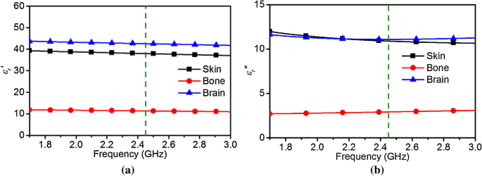
must be known. The complex permittivity parameters for different biological tissues can be found in18. The real and imaginary parts of the permittivity for the considered bio-tissues are
depicted in Fig. 1. For this work, a frequency _f_1 = 2.45 GHz is chosen as it is close to the upper bound of the optimal range for human head tissues. A simplified inhomogeneous head model
consisting of three layers (i.e. skin, bone, brain) is considered. The wavelength _λ__x_ for frequency _f_1 in different biological tissue can be calculated using: $$\lambda_{x} =
\frac{{c_{0} }}{{f_{1} \sqrt {\varepsilon_{x} } }}$$ (1) To characterize the wave propagation inside the layered biological tissues at frequency _f_1, the reflections occurring at each
interface can be combined to achieve overall reflection coefficient utilizing: $$\Gamma_{overall} \cong \Gamma_{0} + \sum \Gamma_{x} e^{ - j2x\theta }$$ (2) where, \(\theta = \frac{2\pi
}{{\lambda_{x} }}d_{x}\) for each layer with tissue thickness _d__x_, and \(\Gamma_{0}\) is the reflection coefficient at the boundary of air and skin. The specific reflection coefficient at
the interface between different materials can be found using the normalized Fresnel equation for reflection: $$\Gamma_{x} = \frac{{\eta_{x + 1} - \eta_{x} }}{{\eta_{x + 1} + \eta_{x} }}$$
(3) where, $$\eta_{x} = \frac{{\eta_{0} }}{{\sqrt {\varepsilon_{x} } }}$$ (4) \(\eta_{0}\) is the wave impedance of free space, \(\eta_{x}\) and \(\eta_{x + 1}\) are the impedances of the
incident and transmitted wave materials respectively. For the considered tissue materials, the wave impedances can be found in Table 1. Once the overall reflection coefficient is found using
(2), the wave impedance of the overall layered biological structure \(\eta_{overall}\) can be found using the general form of the reflection coefficient equation: $$\eta_{overall} = -
\eta_{0} \left( {\frac{{1 + \frac{1}{{\Gamma_{overall} }}}}{{1 - \frac{1}{{\Gamma_{overall} }}}}} \right)$$ (5) As a rectangular waveguide is to be used as the radiation source, the wave
impedance of the dominant TE10 mode can be determined using: $$\eta_{TE} = \frac{{\left| {\eta_{overall} } \right|}}{{\sqrt {1 - \left( {\frac{{f_{c} }}{{f_{1} }}} \right)^{2} } }}$$ (6)
where _f__c_ is the cut-off frequency of the waveguide. Owing to the irremovable conductivity of the biological tissues, the conductive material loss of a propagating wave inside the human
head cannot be minimized. However, by matching \(\eta_{TE}\) with \(\eta_{overall}\) at the outer boundary of the layered biological structure, maximum power penetration inside human head is
possible. This matching can be achieved by utilizing a dielectric loaded rectangular waveguide filled with a material of permittivity, _ε__wg_. Utilizing the wave impedance of the TE wave
in (6), the _ε__wg_ required can be found from: $$\varepsilon_{wg} = \left( {\frac{{\left| {\eta_{overall} } \right|}}{{\eta_{TE} }}} \right)^{2}$$ (7) By utilizing the equations, the
dielectric loaded rectangular waveguide permittivity _ε__wg_ is found to be 3.6 − j5.8 at 2.45 GHz. The imaginary part of the permittivity contributes to the loss of the material, which if
included in the waveguide dielectric material will introduce more loss to the overall system. Thus utilizing just the real part of the permittivity _ε__wg_ becomes 3.6 at 2.45 GHz.
SIMULATION SETUP To evaluate the validity of the calculated result, a Computer Simulation Technology (CST) Microwave Studio19 simulation setup as depicted in Fig. 2 is adopted. The complex
permittivities and thicknesses of the human tissue materials are set to those stated in Table 1. The broad wall dimension of the dielectric filled rectangular waveguide, _a_, is calculated
via: $$f_{{cTE_{10} }} = \frac{c}{{2a\sqrt {\mu_{m} \varepsilon_{m} } }}$$ (8) where _f__c_ is the selected cut-off frequency, _μ__wg_ and _ε__wg_ are the permeability and permittivity of
the dielectric filling material, and _c_ is the speed of light in free space. Once the _a_ is found, the short wall dimension _b_ is found as: $$b \le \frac{a}{2}$$ (9) A cut-off frequency
of 1.7 GHz was selected to mimic that of an air filled WR430 waveguide, and the dimensions are found to be _a_ = 47 mm and _b_ = 23 mm_._ In the CST 3D schematic shown in Fig. 3, the open
end of the quartz loaded rectangular waveguide is attached directly to the surface of the skin layer. There is no air gap, or any other material considered at the interface to the phantom.
An open boundary with added space condition from all sides of the phantom and waveguide is considered for simulation. Multiple E-field probes within the CST simulator are placed inside the
human phantom at 50 mm radius from the epicenter of the waveguide-phantom interface to achieve a measure of the E-field intensity at 50 mm inside the head model from the waveguide-skin
interface (Fig. 4). RESULTS AND DISCUSSION Figure 5 shows the reflection coefficient of three different setups; i.e. (1) a phantom consisting of only the skin layer, (2) skin and bone, and
(3) skin, bone and brain attached to the open end of the dielectric loaded waveguide respectively. The reflection coefficient shows the lowest response when all tissue layers (skin → bone →
brain) are attached together at the interface as the dielectric loaded waveguide is designed to interface to this particular configuration of the human head phantom. The simulated normalized
_x_-directed electric-field (_E-field_, _E__x_) penetration at 2.45 GHz is shown in Fig. 6 at 50 mm inside the head model from the surface of the skin for different permittivity dielectric
loaded rectangular waveguides. For each change of permittivity, the waveguide dimensions were changed accordingly to maintain the same cut-off frequency. The maximum field penetration occurs
when the rectangular waveguide dielectric permittivity, _ε__wg_, is within the range of 3 to 4. A frequency sweep from 1.7 to 3 GHz in Fig. 7 shows the normalized _E__x_ penetration
performance for different _ε__wg_ from 1 to 5. The maximum E-field penetration occurs at _ε__wg_ = 3.6 over the entire range, but is particularly pronounced at the lower frequencies.
Although the dielectric characteristics of human head may change slightly with frequency, it can be observed that over the small range of frequencies of interest the E-field penetration is
maximised at the calculated value of 3.6. The penetration is primarily minimum when the permittivity of air (_ε__air_ = 1) is used inside the waveguide. Figure 8 portrays the simulated
normalized _E-plane_ (containing the electric field vector) and _H-plane_ (containing the magnetic field vector) near field patterns at 50 mm distance inside the human head for the waveguide
dielectric filling of 1 and 3.62 respectively. The resulting radiation beam inside the brain is highly directional when permittivity of 3.62 is used compared to the air-filled waveguide.
Hence improved directivity inside the human brain is achieved by using the optimized dielectric filled waveguide. The power penetration \(\vec{P}\) in the propagation direction at a specific
location can be calculated using the cross product of the \(\overrightarrow {E }\) and \(\vec{H}\)-field at a specific frequency. To observe the different transverse mode propagation
characteristics inside the human head, Fig. 9 compares the power penetration for a TEM plane wave with TE10 waves radiating from both an air-filled waveguide and an _ε__wg_ = 3.6 dielectric
filled waveguide. The highest penetration up to a 50 mm distance inside human head occurs when radiated from the dielectric loaded waveguide. The TE10 wave emanating from the air-filled
waveguide exhibits 3–7 dB less penetration and is also lower than TEM propagating wave from air into the human head. The loss due to the high-water content of the brain and other tissues can
be observed from the penetration power level difference of around 20 dB between 0 and 50 mm inside the head. Apart from the dominant mode, higher order modes appear evanescent and hence do
not extend any substantial distance from the edge of the open-ended waveguide and hence do not have significant effect on the field measured inside the human brain. Figure 10 portrays the
simulated axial ratio of the dielectric loaded rectangular waveguide. An axial ratio of 40 dB is achieved indicating a negligible amount of cross polarized fields at 2.45 GHz. As human head
tissue thicknesses vary between people, it is imperative to verify the behavior of the waveguide considering this difference. Figure 11 shows the reflection coefficient of the dielectric
loaded rectangular waveguide for different thicknesses of each human head phantom material as compared to the baseline value in Table 1. For a 0.5 mm thickness difference in the skin layer,
the reflection coefficient shows a determinate amount of variation. The reflection coefficient becomes as low as − 8.44 dB at 2.45 GHz for 0.5 mm skin thickness. With the increment in
thickness of the skin, the reflection coefficient become comparatively higher at 2.45 GHz amounting to − 6.4 dB and − 5.02 dB for 1 mm and 1.5 mm skin thicknesses respectively. As the high
dielectric constant skin layer is the only layer that is in direct contact with the open end of the waveguide, it is intuitive that it would be sensitive to normal human variation. Figure
11b shows the reflection coefficient with changes in bone thickness of human head phantom. Reflection coefficient variation due to a bone thickness is not as significant as compared to skin
thickness. The change in thickness of the brain layer is negligible for increments of 5 mm as shown in Fig. 11c. To validate the performance described in the previous section, an
inhomogeneous human head phantom is fabricated. The composition of tissue mimicking composites used in the fabrication process are shown in Table 2. For the oil concentration, a mixture of
50% Kerosene oil and 50% Safflower oil is used. The procedure presented in20 is utilized to make tissue-mimicking layers of the desired permittivity and loss tangent (_tanδ_). To achieve the
same permittivity as the skin, bone and brain, an oil percentage of 32%, 70% and 28% were used according to20. The characteristics of the phantom tissues fabricated for this experiment
maintain their properties for at least two months. The fabricated phantom materials are measured according to the procedure presented in21 to determine the permittivity and _tanδ,_ and the
results are depicted in Fig. 12a,b respectively. To achieve inhomogeneous performance from the phantom, the brain mimicking material is made first and left to set for 5 days in a plastic
container. Next, bone mimicking material is poured in the plastic container up to the desired thickness level and left for 5 days to solidify. Finally, the skin layer is formed on top of the
bone layer, and again left for 5 days to cure. The resulting inhomogeneous phantom is depicted in Fig. 12c. In order to elucidate the development of the antenna, a numerical analysis of its
performance is carried out layer by layer while attached to the dielectric loaded waveguide. First, only the ground plane and the probe (_Layer 1_) is examined. The probe feeding technique
is utilized by creating a hole through the ground plane, as side feeding technique is not physically suitable for waveguide excitation. The probe is electrically small at 2.45 GHz, and hence
no resonance is found at the desired frequency as depicted in Fig. 13. With the addition of the L-probe (_Layer 2_), a resonance is achieved at 2.52 GHz. Once a rectangular patch (_Layer
3_) is implemented 1.9 mm above _Layer 2_ to achieve increased directionality at the desired frequency, the resonance of the antenna is shifted to 2.45 GHz with optimal patch dimensions. The
1.9 mm gap between the _Layer 2_ and _Layer 3_ is realized by using a layer of Rogers RT/duroid 6010 material of 1.9 mm thickness. A 47 × 23 × 54.65 mm3 quartz block with the permittivity
of 3.75 and _tanδ_ of 0.0004 is selected as the closest suitable material to realize the approximate permittivity of the dielectric loaded waveguide calculated earlier. A copper sheet of 0.5
mm thickness is enfolded around the quartz block to realize the waveguide tube. The constituent components shown in Fig. 14a were assembled, and a waveguide flange with the dimension of
0.25 _λ_2.45 GHz at all sides is realized using aluminium as depicted in Fig. 14b. The side view of the fabricated waveguide is shown in Fig. 14c, showing a waveguide frame made of
transparent plastic to hold the constructed waveguide to its rectangular shape. An antenna feeding technique is utilized to excite the waveguide. Although such a feeding technique lacks
broadband performance, the complication of probe feeding a rectangular waveguide via a hole in the fragile quartz block can be avoided by using this method. Moreover, the findings of this
research are focused at the specific frequency of 2.45 GHz, so a broadband solution is not required. The physical structure of the antenna is shown in Fig. 15. An L-probe technique is
adopted to feed the rectangular patch. Two layers of Rogers RT6010 with relative permittivity of 10.2 and thickness of 1.9 mm is used as the substrate material for the antenna. A 50 Ω SMA
connector is used to connect the L-probe and the ground plane. The dimensions of the antenna are optimized to operate at 2.45 GHz while acting as a feed for the dielectric waveguide, in
contact with the quartz block and covering one aperture end (as seen in Fig. 14). The simulated and measured |S11| response of the dielectric rectangular waveguide with patch antenna feed is
depicted in Fig. 16. The |S11| performance shows good agreement with only ~ 1% shift in the resonant frequency, which can be attributed to the fabrication tolerances of the waveguide and
feed antenna. The simulated and measured realized gain radiation pattern of the open-ended quartz loaded waveguide in free space is depicted in Fig. 17, also exhibiting good agreement in
shape with a minor disparity in their maximum values. The simulated radiation patterns show a front to back ratio (FBR) of 14.2 dB, whereas the measured results achieve a FBR of 14 dB. The
minor discrepancy in the measured FBR may be partially be attributed to the manual handling of measurement whilst changing the orientation of the waveguide on the turn table of the anechoic
chamber. A measurement setup is implemented which includes the inhomogeneous head phantom, the rectangular waveguide excitation source, an electrically small monopole probe, an Anritsu
(MS4644B) vector network analyser (VNA), and a computer as shown in Fig. 18. The same setup is utilized for both the quartz loaded waveguide and a standard WR 430 waveguide to obtain a
comparison. The input power was adjusted to achieve same output power at the aperture for the different waveguides. The power penetration for each waveguide is then measured by placing it
against the inhomogeneous human head without any air gap. The electrically small monopole probe is utilized as an E-field probe for radiation pattern measurement in both E- and H-planes. The
monopole probe is fabricated from a semi-rigid coaxial cable, and the angle of measurement for the radiation pattern is changed manually by inserting the probe into the human head phantom.
The received power is measured via the probe at 50 mm radius from the centre of the waveguide aperture which is mounted flush to the surface of the skin mimicking layer of the inhomogeneous
phantom. The near field power radiation pattern at both E-plane and H-plane for both the dielectric loaded and standard WR430 waveguide is depicted in Fig. 19. The measured results follow a
similar form as predicted in the simulations seen in Fig. 8, with the dielectric loaded waveguide showing enhanced directivity. A power penetration increment of 1.33 dB is achieved utilizing
the quartz loaded waveguide at the boresight direction. Moreover, due to the use of the high dielectric material compared to air the waveguide source shrank significantly compared to the
standard WR430 waveguide, with an 81.9% decrease in aperture size. The measured power penetration performance validates this wave impedance matching technique for increasing the power
penetration into the human head for microwave medical diagnostic systems. To aid clarity, a comparison between the simulated and measured power penetration pattern inside the human head
phantom is shown in Fig. 20. The measured power penetration pattern in the E-plane is following similar pattern to that predicted in the simulation, although with a slightly broader beam at
higher angles from broadside. A half power beamwidth (HPBW) of 30° is exhibited in the simulated E-plane pattern, whereas a 34° HPBW results from the measured pattern. Similarity in the
H-plane power penetration pattern is also very good with a HPBW of 30° evident in both the simulated and measured patterns. CONCLUSIONS Improvement of the microwave power penetration inside
an inhomogeneous human head phantom is achieved by utilizing a dielectric loaded rectangular waveguide for microwave medical diagnostic applications. The combined complex reflection
properties of a layered human head model are calculated between skin, bone and brain tissue. A wave impedance matching technique is applied by utilizing a dielectric loaded rectangular
waveguide to modify the TE10 mode characteristics at 2.45 GHz. An antenna fed Quartz (_SiO_2) loaded rectangular waveguide is fabricated along with a layered inhomogeneous human head phantom
to measure the power penetration. A measured 1.33 dB power penetration increment is achieved at 50 mm inside the human head phantom by utilizing the designed dielectric loaded waveguide as
compared to the standard WR430 waveguide filled with air, and an 81.9% reduction in the aperture size is also attained. REFERENCES * Mobashsher, A. T. & Abbosh, A. On-site rapid
diagnosis of intracranial hematoma using portable multi-slice microwave imaging system. _Sci. Rep._ 6, 37620 (2016). Article ADS CAS Google Scholar * Rokunuzzaman, M., Samsuzzaman, M.
& Islam, M. T. Unidirectional wideband 3-D antenna for human head-imaging application. _IEEE Antennas Wirel. Propag. Lett._ 16, 169–172. https://doi.org/10.1109/LAWP.2016.2565610 (2017).
Article ADS Google Scholar * Bahrami, H., Mirbozorgi, S. A., Ameli, R., Rusch, L. A. & Gosselin, B. Flexible, polarization-diverse UWB antennas for implantable neural recording
systems. _IEEE Trans. Biomed. Circuits Syst._ 10(1), 38–48 (2016). Article Google Scholar * Li, X., Jalilvand, M., Sit, Y. L. & Zwick, T. A compact double-layer on-body matched bowtie
antenna for medical diagnosis. _IEEE Trans. Antennas Propag._ 62(4), 1808–1816 (2014). Article ADS Google Scholar * Casu, M. R. _et al._ A COTS-based microwave imaging system for
breast-cancer detection. _IEEE Trans. Biomed. Circuits Syst._ 11(4), 804–814 (2017). Article Google Scholar * Mobashsher, A. T., Mahmoud, A. & Abbosh, A. Portable wideband microwave
imaging system for intracranial hemorrhage detection using improved back-projection algorithm with model of effective head permittivity. _Sci. Rep._ 6, 20459 (2016). Article ADS CAS
Google Scholar * Poon, A. S., O’Driscoll, S. & Meng, T. H. Optimal frequency for wireless power transmission into dispersive tissue. _IEEE Trans. Antennas Propag._ 58(5), 1739–1750
(2010). Article ADS Google Scholar * Robel, M., Ahmed, A., Baum, T. & Rowe, W. Compact 3-D antenna for medical diagnosis of the human head. _IEEE Transactions on Antennas and
Propagation_, pp. 1–10 (2019). * Chandra, R., Zhou, H., Balasingham, I. & Narayanan, R. M. On the opportunities and challenges in microwave medical sensing and imaging. _IEEE Trans.
Biomed. Eng._ 62(7), 1667–1682 (2015). Article Google Scholar * Mobashsher, A. & Abbosh, A. Compact 3-D slot-loaded folded dipole antenna with unidirectional radiation and low impulse
distortion for head imaging applications. _IEEE Trans. Antennas Propag._ 64(7), 3245–3250 (2016). Article ADS Google Scholar * Mobashsher, A. T., Bialkowski, K., Abbosh, A. & Crozier,
S. Design and experimental evaluation of a non-invasive microwave head imaging system for intracranial haemorrhage detection. _PLoS One_ 11(4), e0152351 (2016). Article CAS Google Scholar
* Rezaeieh, S. A., Zamani, A. & Abbosh, A. 3-D wideband antenna for head-imaging system with performance verification in brain tumor detection. _IEEE Antennas Wirel. Propag. Lett._ 14,
910–914 (2015). Article ADS Google Scholar * Mobashsher, A. T., Abbosh, A. M. & Wang, Y. Microwave system to detect traumatic brain injuries using compact unidirectional antenna and
wideband transceiver with verification on realistic head phantom. _IEEE Trans. Microw. Theory Tech._ 62(9), 1826–1836 (2014). Article ADS Google Scholar * Mobashsher, A. T., Bialkowski,
K. S. & Abbosh, A. M. Design of compact cross-fed three-dimensional slot-loaded antenna and its application in wideband head imaging system. _IEEE Antennas Wirel. Propag. Lett._ 15,
1856–1860 (2016). Article ADS Google Scholar * Takook, P., Persson, M., Gellermann, J. & Trefná, H. D. Compact self-grounded Bow-Tie antenna design for an UWB phased-array
hyperthermia applicator. _Int. J. Hyperth._ 33(4), 387–400 (2017). Article CAS Google Scholar * Salama, R., Kharkovsky, S., Liyanapathirana, R. & Gunawardana, U. Wireless power
transmission in human tissue for nerve stimulation. _IET Microw. Antennas Propag._ 10(6), 670–675 (2016). Article Google Scholar * Whittall, K. P. _et al._ In vivo measurement of T2
distributions and water contents in normal human brain. _Magn. Reson. Med._ 37(1), 34–43 (1997). Article CAS Google Scholar * Hasgall, P., Neufeld, E., Gosselin, M., Klingenböck, A. &
Kuster, N. IT’IS Database for thermal and electromagnetic parameters of biological tissues, _Version 2.6_ (2015). * Computer Simulation Technology (CST). Dassault Systemes.
https://www.cst.com/ (Accessed 5 May 2020). * Lazebnik, M., Madsen, E. L., Frank, G. R. & Hagness, S. C. Tissue-mimicking phantom materials for narrowband and ultrawideband microwave
applications. _Phys. Med. Biol._ 50(18), 4245 (2005). Article Google Scholar * Baum, T., Thompson, L. & Ghorbani, K. Complex dielectric measurements of forest fire ash at X-band
frequencies. _IEEE Geosci. Remote Sens. Lett._ 8(5), 859–863 (2011). Article ADS Google Scholar Download references AUTHOR INFORMATION AUTHORS AND AFFILIATIONS * School of Engineering,
RMIT University, Melbourne, VIC, 3001, Australia Md. Rokunuzzaman, Asif Ahmed, Thomas Baum & Wayne S. T. Rowe Authors * Md. Rokunuzzaman View author publications You can also search for
this author inPubMed Google Scholar * Asif Ahmed View author publications You can also search for this author inPubMed Google Scholar * Thomas Baum View author publications You can also
search for this author inPubMed Google Scholar * Wayne S. T. Rowe View author publications You can also search for this author inPubMed Google Scholar CONTRIBUTIONS M.R. conceived the idea
and designed the structure. M.R., A.A. and T.B. developed the methodology. The electromagnetic simulations and the calculations were carried out by M.R., A.A. and W.R. M.R. wrote the entire
manuscript with the input from W.R., T.B. and A.A. All the authors reviewed the manuscript. CORRESPONDING AUTHOR Correspondence to Md. Rokunuzzaman. ETHICS DECLARATIONS COMPETING INTERESTS
The authors declare no competing interests. ADDITIONAL INFORMATION PUBLISHER'S NOTE Springer Nature remains neutral with regard to jurisdictional claims in published maps and
institutional affiliations. RIGHTS AND PERMISSIONS OPEN ACCESS This article is licensed under a Creative Commons Attribution 4.0 International License, which permits use, sharing,
adaptation, distribution and reproduction in any medium or format, as long as you give appropriate credit to the original author(s) and the source, provide a link to the Creative Commons
licence, and indicate if changes were made. The images or other third party material in this article are included in the article's Creative Commons licence, unless indicated otherwise
in a credit line to the material. If material is not included in the article's Creative Commons licence and your intended use is not permitted by statutory regulation or exceeds the
permitted use, you will need to obtain permission directly from the copyright holder. To view a copy of this licence, visit http://creativecommons.org/licenses/by/4.0/. Reprints and
permissions ABOUT THIS ARTICLE CITE THIS ARTICLE Rokunuzzaman, M., Ahmed, A., Baum, T. _et al._ Microwave power penetration enhancement inside an inhomogeneous human head. _Sci Rep_ 11,
21793 (2021). https://doi.org/10.1038/s41598-021-01293-4 Download citation * Received: 31 May 2021 * Accepted: 19 October 2021 * Published: 08 November 2021 * DOI:
https://doi.org/10.1038/s41598-021-01293-4 SHARE THIS ARTICLE Anyone you share the following link with will be able to read this content: Get shareable link Sorry, a shareable link is not
currently available for this article. Copy to clipboard Provided by the Springer Nature SharedIt content-sharing initiative